This guide covers almost any of the 150cc buggies, scooters, or ATV's with the standard "AC" CDI setup. The first version was downloaded over 136,494 times and we're happy that this information continues to help so many people!
Getting started: How it all works
The 150cc GY6 ignition system is fairly easy to troubleshoot in the case of malfunction. There are 4 major components that work together to produce spark, if any of these are defective spark will be lost. What we will be doing here is troubleshooting these ignition parts starting at the source, and working towards the spark plug.
Major Ignition Components
- Stator (6th winding and trigger pickup module)
- CDI unit
- Ignition coil
- Spark plug
To diagnose your ignition system, you will need to do each of the steps in this article, in sequence.
Basic GY6 Diagram
Before getting started, take a look at this diagram. Although there are many differences in wiring between models, most GY6 ignition systems work the same as shown in this illustration. You'll want to come back to this for reference throughout the guide.

CDI Pinout Diagram
We'll stick our CDI pinout diagram right here so you'll have access to it for the steps below.

FIRST STEP: BYPASS YOUR SWITCHES
A very common cause of no spark is a defective ignition or kill switch. Before beginning to troubleshoot ignition problems, it is best to bypass the switches.
How to bypass your switches
- Create a jumper wire from pin #4 directly to a good grounding spot on the engine.
- Being very careful not to deform or break the pin,remove the #5 wire from the CDI plug at the harness. This can be done with a sharp narrow tool like an ice pick or stiff paper clip. Looking from the front of the plug, you will see small metal tabs on each pin which secure them to the plug. Push the tab down and the pin will release. Don't use force here.
TEST 1: STATOR
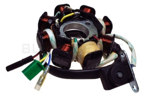
Note the wrapped ignition winding, and trigger module
Ignition Winding:
Depending on your stator type, you have either 6, 8, or 11 windings. Of these windings, one is dedicated to supplying the CDI with ignition power. This winding is usually wrapped in white cloth material and sealed over with clear epoxy.
Trigger pickup:
A simple type of crankshaft position sensor. Sends a signal to the CDI to let it know when to send fire to the plug.
Troubleshooting the Stator:
- Set your multimeter to read in VOLTS "AC".
- Locate and disconnect the Black/Red and Blue/Yellow wires coming from the stator, where they plug into the main engine harness. (These are both bullet-style connectors)
- While cranking the engine, use a multimeter to check for voltage coming from the Red/Black (CDI power wire) and the Blue/Yellow (trigger wire) coming from stator. Place the black lead of multimeter on a metal surface of the engine while using the red lead on the tips of the wires.
- There should be between 20vAC ~ 100vAC coming from the CDI power wire (Black/Red), although much lower voltages will still be able to produce spark.
- There should be at least 0.05vAC coming from the trigger wire (Blue/Yellow).
- Write the voltages down and continue to the next step.
Minimum values:
Stator output: 20vAC minimum
Trigger output: 0.01vAC minimum
STEP 2: THE CDI UNIT
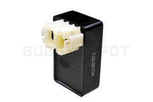
Typical GY6 CDI Box
The CDI Unit is powered by the AC current coming from the wrapped stator winding. This current is stored in a capacitor within the CDI unit. When a signal is received by the trigger pickup passing over the flywheel magnet, the CDI will discharge the stored energy into the wires leading to the ignition coil.
Troubleshooting the CDI:
- Ensure your multimeter is set to read in VOLTS "AC".
- Just like before: while cranking the engine, use a multimeter to check for voltage at the two primary wires of the ignition coil. Connect your back multimeter lead to the black ground wire at the coil, and with the red lead to the lighter color wire (usually blue or purple, but it varies). At this step we are checking to see exactly what the CDI is outputting. Write the voltages down and continue to the next step.
Minimum values:
CDI output: Can be 5% to 30% less than the output from the stator. The minimum we have seen working is around 18vAC.
STEP 3: THE IGNITION COIL
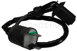
Black is neutral, green is input from the CDI
The function of the ignition coil is to multiply the voltage of the power supplied from the CDI, and to send the multiplied power to the spark plug.
Troubleshooting the Ignition Coil:
Check for 0.1 ohm ~ 1.0 ohm across the two primary coil terminals. This isn't exactly definitive, as we have seen working coils with 0.0ohms resistance. The best way to tell if the coil is bad is to perform steps the steps above. If there is still no spark, the coil is likely bad.
STEP 4: SPARK PLUG
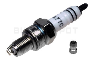
Check for proper plug gap!
The plug is very rarely the cause of no spark on the GY6. If the plug is fouled or cracked it may not spark. Ensure that the spark plug is gapped properly.Recommended spark plug gap: 0.6mm ~ 0.7mm (0.23″ ~ 0.27″)
Was this guide helpful?
Please consider supporting this article and our efforts to provide the best technical support to the GY6 community. We have all of these parts. Buggy Depot – Select your vehicle. Thank you!
Posted by: darrelldarrellbarberoe0267317.blogspot.com
Source: https://www.buggydepot.com/tech-center/gy6-150cc-ignition-troubleshooting-guide-no-spark/


0 Comments